-
Notifications
You must be signed in to change notification settings - Fork 17
Home
!!!! ***** UNDER CONSTRUCTION ***** !!!!
Geometry Description Markup Language (GDML) is a specialized XML-based language used to specify
Geometries for Monte Carlo Simulation software such as ROOT, Geant4, etc see GDML Manual.
It defines a rich set of Solid Computer Graphic Objects for details of GDML Solids
The GDML Workbench lets the user
- Import
- View
- Edit
- Create
- Export
Such Geometries.
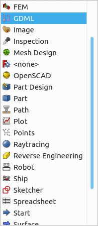
From the FreeCAD command bar select View | Workbench then select GDML

It is recommended that when you have the GDML workbench active that the following Toolbars are viewable
- Workbench
- Structure
- GDMLTools
- GDML Part Tools
So Icons displayed should look similar to the following
![]()
To make a Toolbar viewable, from the FreeCAD command bar select View | Toolbars
GDML Solids are implemented as FreeCAD Python Objects and have the same properties as defined by GDML. By selecting an Object the properties can be changed via the FreeCAD properties windows and the resulting changes displayed.
Short decription
Short decription
Short decription
Short decription
Short decription
Short decription
Short decription
Given a lot more solids are supported for import, it is not too difficult to add more, so if you feel you need a particular solid to be added please contact me.
Select two Parts/Logical Volumes and then click on the appropriate boolean icon
- Import GDML file
- Scan GDML file - Facility for dealing with large GDML files
When creating a new file from the GDML workbench the file Defaults.gdml is read from the Resources directory, this may or may not have material definitions, as supplied there are none.
A Materials Group called Geant4 is created by reading the file Geant4Materials.xml from the Resources directory which define all the materials that GEANT4 implicitly defines by default.
When a file is exported the default behaviour is to ignore materials in the geant4 groups as GEANT4 implicitly defines these.
If you need the Geant4 materials for use in a none GEANT4 situation, for example ROOT then you can set the Workbench preference to export used Geant4 materials

Any materials in the non Geant4 Group should be exported.
User define materials can be added to a model by importing a xml file with File | Import.
The file needs to be formatted as follows
<xml>
    <materials>
        ...... ( Can contains Isotopes, Elements, Material definitions )
    </materials>
<xml>
If you have the materials in an existing cdml file then you should be able to
- Import the GDML file.
- Select the Materials Group
- File | Export
- set a file name and extension of xml
You can then import the exported file into a new model.
In addition to the GDML solids, the GDML Workbench supports the export of a subset of the solids one can create in the FreeCAD Parts Workbench. These are documented below. For those shapes not directly supported for export, the recommended way to proceed is to take the resulting BREP (Boundary Representation) Shape and then translate it to a GDML Tessellate, or use some software like McCad to decompose the BREP Shapes into GDML Objects.
The GDML Workbench provides a number of facilities to
-
Export FreeCAD(BREP) shapes as GDML Tessellated Objects.
-
Allocate a GDML Material and directly Convert a FreeCAD(BREP) Shape to a GDML Tessellated Object
using a number of different algorithms- Standard FreeCAD mesh facilties
- Gmsh
- Tetrahedron (This does not directly translate to GDML, but to a GDML Assembly of GDML Tetra)
Shapes created by the Sketch Workbench and extruded via the Part Extrude command can be exported to GDML. The exrusion must be added to a Part under the worldVol tree. Currently extrusion exports have the following limitations: (1) only extrusions along the z-axis are supported (i.e., the sketches must be in the x-y plane). Note that this does not pose a real limitation, since the extrusion object itself can be rotated or translated to any desired orientation or location. (2) Arcs/elliptical whose chords are crossed by lines (or other arcs) cannot currently be processed. Arcs/lines that are completely inside or outside other arcs, are supported, though. Examples of Extruded sketches are in Extruded sketches examples
Technical Notes: extrusions are exported as a sequence of booleans of intrinsic GDML objects. BSplines are discretized as a sequence lines and exported as an <xtru solid. The exported xtru can be made smoother (more points) as follows: select the extrusion object, then select its View property Panel. Right click on the Display Options header and check the 'Show All' check box. This will reveal additional properties that can be set. One of them is 'deviation', which defaults to 0.5 (%). Decrease that nummber to get smoother curves. You may increase it to get coarser curves. FreeCAD does not support Deviation values larger than 0.5, but the GDML extruder can use larger values.
Tests comparing the performance of geant simulations with extuded sketches vs their tesselated versions have shown the extrusions to be 2-5 times faster than their tessellations.
Please note that reimporting an exported GDML will expose the constructed booleans so not look the same as the FreeCAD that was exported.
Shapes created by the Sketch Workbench and revolved via the Part Revolve command can be exported to GDML. The revolution must be added to a Part under the worldVol tree. Currently revolution exports have the following limitations: (1) only revolutions around the z-axis are supported and (2) the sketches must be in the x-z plane. Note that this does not pose a real limitation, since the revolved object itself can be rotated or translated to any desired orientation or location. Examples of revolved sketches are in Revolved sketches examples
Technical Note: All curves in a revolved sketch, except circles, are discretized and exproted as <polycone's. Circles are exported as a torus. Booleans of these are used to fully construct the revolved sketch. The smoothness of the discretization can be changed as described above, under Extruded Sketches.
Please note that reimporting an exported GDML will expose the constructed booleans so not look the same as the FreeCAD that was exported.
Arrays of objects, constructed under the Draft Array command, or the GDML Array command can be exported as GDML objects. The arrays must be of currently supported objects (GDML, or Part objects, such as extrusions, or revolutions). Arrays of arrays can also be exported. Currently the following types of arrays are supported:
- Ortho(gonal) arrays
- Polar arrays
- Path arrays
- Point arrays
In the future other types of arrays will be supported.
The Array object must be added to a Part under the WorldVolume tree. Note that the array object is exported as a single multiUnion gdml solid. Thus the objects in the array are considered as part of one solid, and hence have one material. It is best practice to assign the material to the Array object. If a material is not assigned to the Array object itself, its (sub)objects are scanned recursivley and the material of the first object that does have a material property is selected.
A mirror of a GDML exportable object (including extrusions, revolutions, arrays) can be created and exported; either using the Draft mirror command, or or the provided GDML short cut. At present the mirrored iobjects (both the original object and its mirror image are exported in a gdml <assembly. They both share the original volume and hence will have the same material. Examples are in Mirror examples. Note that in FreeCAD when a mirrored object is itself mirrored, one only get an additional mirror of the mirrored object, not additionaly a mirror of the original object.
A scaled copy of an exportable object can be exported. The scaling of GDML solids (as opposed to Part shapes, that are not GDML Solids), can be scaled using the Scale Command icon provided with in the GDML Workbench. This command adds a scale property to each of the selected solids; no additional objects are created. In contrast, the Draft scaling operation creates a separate object (must be a clone) that carries the scaling information, while the original object remains in the tree. To export the scaled object, the clone must be added to a Part that is under the WorldVolume tree, while the original object must be outside tha tree (but not deleted, as the clone refers to it). If multiple objects are selected and scaled using the Draft scale operation, all those objects become part of the clone and are exported as GDML multiUnion, and hence will have one and the same material. That material is best assigned to the clone object, but, as in the case of other composite objects, if a material is not provided, the sub-objects will be searched recursively until one is found with a material property, then that material is assigned to the multiUnion. Otherwise a default material (currently G4_STAINLESS-STEEL) will be assigned. A peculiarity of the Draft scale operation is that its placement (rotation and position) are copied from the scaled object, in the case of scaling a single object, and set to the identiy placement in the case of scaling several objects. In either case, the placement property of the clone is its onw and separate from the of the scaled object. Subsequent changes to the placement of the scaled object do not affect the placement of the clone. However, because the GDML Workbench makes use of the original object's placement, changes to those after a scaling operation is performed will affect the exported model, but not the FreeCAD one. Therefore, changing the placement of the original object should not be done after scaling. If it is desired the change the location of the scaled object (the clone), change that placement (not the original), or else delete the clone, move the original and scale again.
To export a GDML file, select the root Part ( GDML World Volume ) then use the standard FreeCAD export facility ( File | Export )
If a filetype of lowercase gdml is selected a single GDML file is produced.
If a filetype of uppercase GDML is selected then the following files are created in a directory derived from the path name less the GDML file extension.
- A [Name].gdml with imbeds for the following xml files
- setup.xml
- constants.xml
- defines.xml
- materials.xml
- [Name]-solids.xml
- [Name]-structure.xml
Note: Provided you have the lxml python library installed, you should be able to successfully open the [Name].gdml file
ROOT only supports GDML defined in a single file, as it does not support the required DOCTYPE !ENTITIES.
There are two options
-
Open the multi file with the workbench and then export with as a single GDML file.
-
Use the standalone python program supplied in Utils
combineGDML.py [input file with imbeds] [output single file]
Such multi files are supported by Geant4.
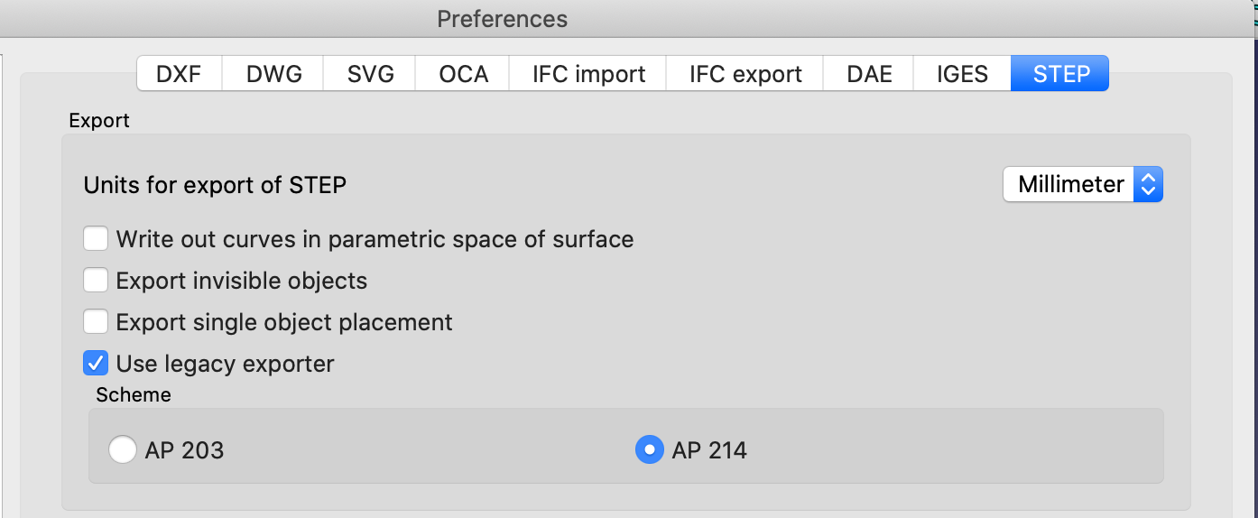
When exporting STEP files that include GDML objects set the FreeCAD Preference for Export to use legacy exporter
