-
Notifications
You must be signed in to change notification settings - Fork 84
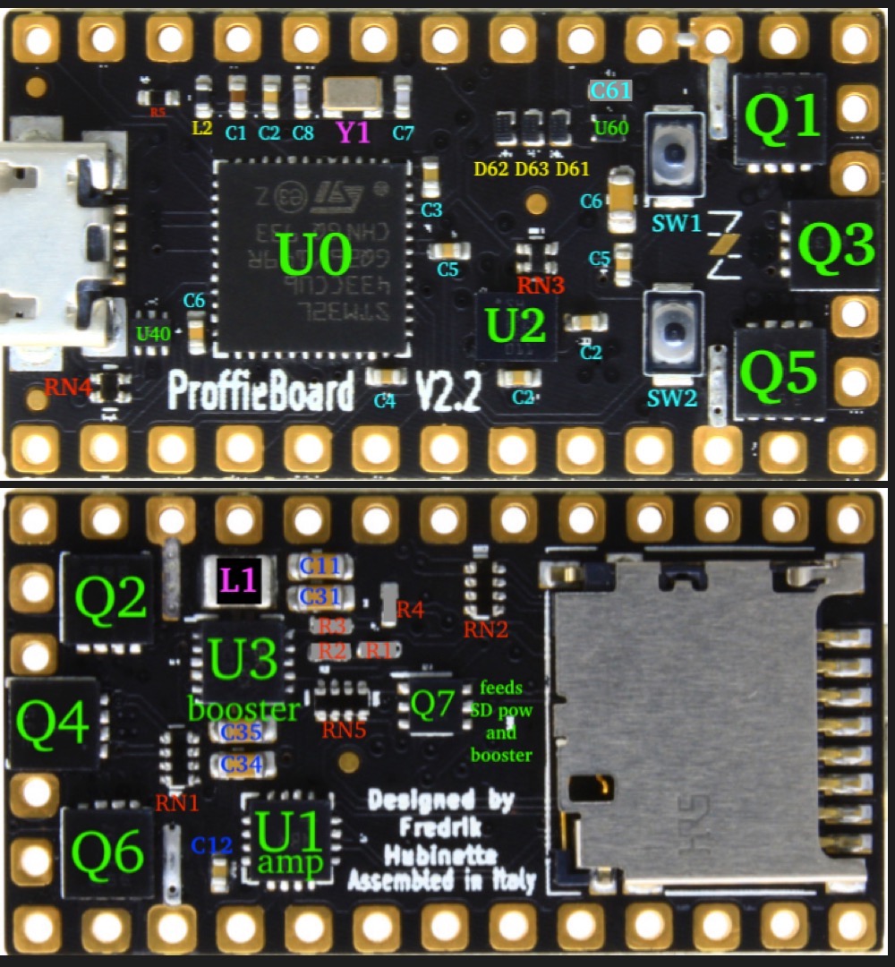
Proffieboard V2.2 Part map Component level
NoSloppy edited this page May 20, 2022
·
3 revisions
These part numbers are referenced in the Bill Of Materials (BOM) for Proffieboard V2.2, which contains links to buy them (when available). It can be found here: https://docs.google.com/spreadsheets/d/18MwtF8ENlrQoEh_lPH9iURkPmyv8qekj8NvmkMRsl70/edit?usp=sharing
As of late, a couple of the parts are coming up as either unavailable or only available in bulk.
There's a running tab of alternative parts here:
https://github.com/profezzorn/ProffieOS/wiki/BOM:-Proffieboard-v2.2-components-and-alternative-parts.
| Part | Description | Notes |
|---|---|---|
| U0 | Main CPU | Does everything |
| U2 | Motion chip | Played when you move the saber around |
| U1 | Audio Amplifier | |
| U3 | Booster | |
| U60 | 3.3V Regulator | Feeds the CPU, SD card |
| L1 | Booster coil | |
| Q7 | Dual pFET | Used to control current to SD card and as reverse-current protection for most of the board. (Except for Q1-Q6) |
| Y1 | Clock crystal | (together with C7/C8) |
| RN4 | USB protection resistors | |
| U40 | USB ESD protection diodes | |
| RN3 | i2C pullup resistors | |
| R5 | Serves two functions: It protect the board from battery power, and also limits how much current the blade pixels can leech from the board when they are supposed to be off. | Can be replaced with a bridge, but the board will be vulnerable unless there is an external resistor somewhere. Note that if you have a pogo pin connector, the resistor should be between the board and the pogo pins, having one in the blade is not sufficient to protect the board. |
| L2 | Filters out noise on the power provided to the CPU. | In most cases, this can be replaced with a bridge. The extra noise is still unlikely to cause problems for the CPU. |
| Q1-Q6 | Controls the power to the LEDs or Pixels. | There are six of these, and if some of them are not used, these become your spares if one of these breaks. So if you short your blade and Q2/Q3 fries, just hook up your blade to LED4/5 instead and update your configuration accordingly. |
| D61 | Prevents current flow to the battery when on USB. | Sometimes, this breaks down in an odd way, where the board will work just fine IF you plug it in to USB to boot it up. While the board can potentially operate if this is replaced with a bridge, it's not safe to do so, and the component must be replaced to make the board work again. |
| RN4 | Protects the USB and CPU from each other. | Can potentially be replaced with two bridges, but the board will be more vulnerable to electrical spikes over the USB connection. Also, if you bridge the pads, make sure to bridge them the right way, or USB communications will not work. |
| SW1 | BOOT button | The board will work just fine without it, until you end up with a bad programming and need to press it. If you remove the button completely, you can short the pads with a paperclip or tweezers when you need to push it. |
| SW2 | RESET button | The board will work fine without it. If it's not working, you can short the reset pad to GND instead. Also, if your goal is to put the board in bootloader mode, you can hold BOOT while providing power to the board instead of holding BOOT while pressing reset. |
| C61 | Battery power noise filter | This capacitor helps filter out incoming noise and helps the 3.3v regulator work properly. It's entirely possible that the board will work without it, especially if you don't have anything extra drawing power from the 3.3v pad. |
Cool Footer
