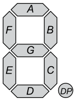
This component let you connect 7-segment display directly to controller using just some resistors.
Just list as many digit_pins as you have. If you have just one digit feel free connect pin to power rail and don't specify this value.
Connect the pins in order of [g, f, e, d, c, b, a, .], if your display does not have decimel point it can be ommited.
Usually driver is turning on whole digit one by one so you need resistors for each segment pin to have the same brightness. So 8 of them.
But if you have 4 digits you can put resistors on the digit side. To achieve the same brightness we have to turn on not whole digit, but the same segments on all digits at the time. To switch to this mode just set iterate_digits to false.
Some displays have degree mark right before the last digit. So you can have 22.4°C or 72.3°F reading. Use degree_pin and set_degree_on(bool) function. Pin becomes HIGH when turned on. Just invert pin if you like to have it LOW when on.
If display has : mark use colon_pin and set_colon_on(bool) function. Pin becomes HIGH when turned on. Just invert pin if you like to have it LOW when on.
Each diode on display has two terminals. Anode is Positive terminal, Cathode is negative. To select your display type use display_type config option. Default value is common_anode, set it to common_cathode to change it.
Common Anode displays has Anodes of each digit connected together and exposed as digit pins. Cathodes of each segment connected and exposed as segment pins. To display one digit we should select the digit by setting HIGH level on its pin and LOW on all other digits. To select segments to turn on we set segment pins we need to LOW and rest segment pins to HIGH.
Common Cathode display activiation routine works the same but levels are inverted. Digit selected by LOW level and serments by HIGH.
To show different numbers we have to turn them on one by one.
This example of wiring 4 digit 7-segment common anode display to S2 mini. This example will not work with original ESP32 becaues pins 34-39 are read-only there.
- Display segment pins [
g,f,e,d,c,b,a,.] connected directly to pins [21, 40, 14, 10, 36, 17, 34, 8] - Display digit pins connected via 220 Ohm resistors to pins [1, 2, 6, 4]
- Display colon anode connected to pin 38
- Display colon cathode connected to ground vai 220 Ohm resistor
- Display degree anode connected to pin 13
- Display degree cathode connected to ground via 220 Ohm resistor
external_components:
  source: github://asergunov/7segment_gpio

time:
- platform: sntp
  id: sntp_time

esp32:
  board: esp32-s2-saola-1
  framework:
    type: arduino

display:
- platform: 7segment_gpio
  id: lcd
  digit_pins: [1,2,6,4]
  iterate_digits: false
  segment_pins: [21, 40, 14, 10, 36, 17, 34, 8]
  colon_pin: 38
  degree_pin: 13 # degree mark on
  update_interval: 100ms
  # display_type: common_cathode # Uncomment this line for common cathode display
  lambda: |-
      switch((millis()/3000) % 3) {
      case 0:
        it.printf(0, "%4.1fC", 22.4);
        it.set_degree_on(true);
        it.set_colon_on(false);
        break;
      case 1:
        it.printf(0, "%4.1fF", 72,3);
        it.set_degree_on(true);
        it.set_colon_on(false);
        break;
      case 2:
        it.strftime(0, "%H%M", id(sntp_time).now());
        it.set_degree_on(false);
        it.set_colon_on((millis()/500) % 2);
        break;
      default:
        it.print("Er 1");
        it.set_colon_on(true);
        break;
      }