-
Notifications
You must be signed in to change notification settings - Fork 13
Conversion and measurements
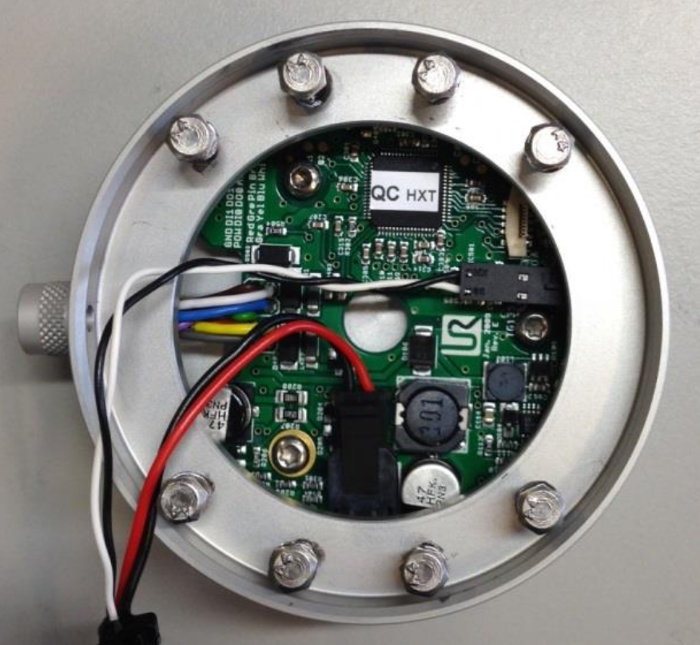
To install the power supply it is necessary to take all tools of the UR5-Robot arm, then take of the last part of the robot. In this part is a board which controls the tool output, the board has a small hole in the middle with a diameter of about a centimetre. Here we drill a hole to lay power supply cable through it. We branch this cable from the power supply from the inside of the robot. After the reinstallation of the tools the cable can be lay out through a hole between the gripper and the force torque sensor. This is possible because the force torque sensor is hollow in the middle.
So the conversion step by step:
- Remove the data and power supply cables from the gripper and the force torque sensor.
- Loosen the six screws at the side under the gripper and take off the gripper. ATTENTION! These are inch screws.
- Take of the force torque sensor, to this loosen the four screws on the sensor.
- Remove the adapter under the ft sensor, also with four screws.
- To take of the tool flange you have to remove the black flexible ring and push the grey ring back. Loosen the 8 screws under the removed coverage. Twist the flange and pull it away from wrist 3. Now disconnect the two cables. For a more detailed description take a look in the UR5 service manual.
- In the next step we drilled a hole in the middle of the cap, due to the hole in the board this is possible. The hole we drilled has a diameter of 3mm.
- Now we need to build a cable that branches the power supply from the arm to supply the board and the new connection we lay to the outside. The power cable were connected to the board, so we attach a new connection in between and add a Y-branch to this connection. We use the new power cable for the connection outside the hand.
- At this point we did the measurements
- The connection for the outside have to pull through the hole of the cab, the other connections stay inside the cab.
- Connect the power cable and the data cable to the board inside the cap and reinstall the cap to the arm.
- Reinstall the adapter and the force torque sensor, both are hollow. In this free space the cable for the outside connection lays. The adapter between the ft sensor and the gripper has a small hole on the side, here you should bring the cable to the outside.
- Mount the gripper and connect the data and power cables.

source: https://s3-eu-west-1.amazonaws.com/ur-support-site/15737/ServiceManual_UR5_en_3.1.2.pdf
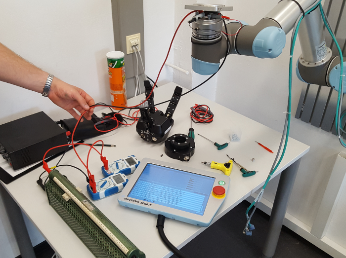
The following picture shows the measuring setup.

We want to test if our new power supply can reach over 1A at 48 Volt without getting an error due to a fuse. So that we are safe when we connect a DC/DC converter from 48V to 24V and use up to 2A. For the measurement we connect two measuring instruments, one for the voltage and one for the current. And a resistor with a range of 0 to 100 Ohm.
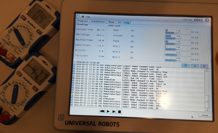
The fist measurement shows the values for the voltage and the current with the maximum resistance of around 100 Ohm. The result is 0.41A at 47.7V. The touch panel of the UR5-Robot shows a current of 1.0A and a voltage of 48.0V, the difference of the current value is due to the rest of the arm, it consumes around 0.6A.

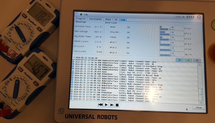
Now we reduce the resistance to check if there is a fuse which prohibits a current over 1A. The measurement shows that we can reach 1.82A with the measuring instrument and 2.3A on the touch panel without any interruption. After the transformation this should lead to 3.6A at 24V which is over our wanted 2A, so we should be safe.

With this result we assume that we can connect a DC/DC converter to get 24V and reach the wanted 2A. With our measurements we must go up to 3A (or probably more) at 24V without any problems.