update - Because KeDei doesn't keep the backward compatibility at all, every "version" of the display has a different LCD panel with different connection. This hack works only with display KeDei module v4.0.
update2 - There's better way than to hack the KeDei displays! There's a LCD module that directly exposes the ILI9488 with no unnecessary intermediate shift registers. This means that we can have the "4-wire 8-bit data serial interface" to ILI9488 without any hacking (we can access pins IM2:0 and set this mode directly). Also, the company that sells this LCD modules seems to take completely different approach - they publish as many info and documentation as possible (KeDei keep everything as secret - at least in English I was not able to google any documentation about their modules). So definitely better approach to business than KeDei. And the price is more or less similar. There's only one disadvantage for ILI9488 users. The ILI9488 by default doesn't support 16 bpp (65k colors) mode in "4-wire 8-bit data serial interface" (although it supports it in parallel modes, which are used in this KeDei LCD display module). So we need to use 18 bpp (262k colors) mode which is a bit slower (more pixel data have to be transferred). See my https://github.com/wdim0/esp8266_fast_lcd_driver_hspi repo.
If you're interrested in this way, here's the link to the LCD module ER-TFT035-6:
http://www.buydisplay.com/default/serial-spi-3-5-inch-tft-lcd-module-in-320x480-optl-touchscreen-ili9488
or you can find these displays on eBay, as always :)
----------
This repository describes an idea of easy hack (depending on your DIY skills) of the cheap KeDei LCD 3.5" module (320x480 pixels), originally sold as a display option for Raspberry Pi, to simulate more standard LCD connection (seen in LCD modules more often) using lines: /CS, D/C, SCLK, MOSI, (MISO), sometimes called as "4-wire 8-bit data serial interface II" or "4-line serial interface".
After the hack, the module can be used with my WLCD driver and ESP8266 for superfast drawing possibility (superfast in ESP8266 terms) - see video with 40 MHz clock.
Why? Because KeDei is cheap, nice, but it's not optimized for speed. At least for ESP8266 and it's HSPI interface and it's long transactions (max. 512 bits / 512 CLK long). The SW subroutines to manage shift register and pulse /CS adds unnecessary slowdown. Why they just didn't set the LCD controller into serial interface mode? (ILI9488's pins IM2:0) Surely the Raspberry Pi could also manage that .. or not?
So basically, if you want to connect KeDei module to ESP8266, you have 3 options:
- use SW bit-banging. Sooo sloooow, useless with 320x480 (153.6 k) pixels
- use module as is and use HSPI to perform some basic HW SPI transactions, but the transactions have to be short - number of transmitted bits must be exactly as KeDei internal shift register (3 x 74HC565 shift registers = 24 bits). Also not optimal for 320x480 pixels at all
- hack the LCD module to get more standard LCD connection type (4-wire 8-bit data serial interface II) and use entire HSPI buffer. This gives us speed. If you're looking for suitable driver, you can use my WLCD driver for superfast drawing possibility (in ESP8266 terms). And that's what we're doing here ;)
ESP8266 @ 80 MHz with hacked 3.5" KeDei LCD module v4.0 with 74VHC4040 (480x320, 16 bpp, HSPI CLK 40 MHz) - video
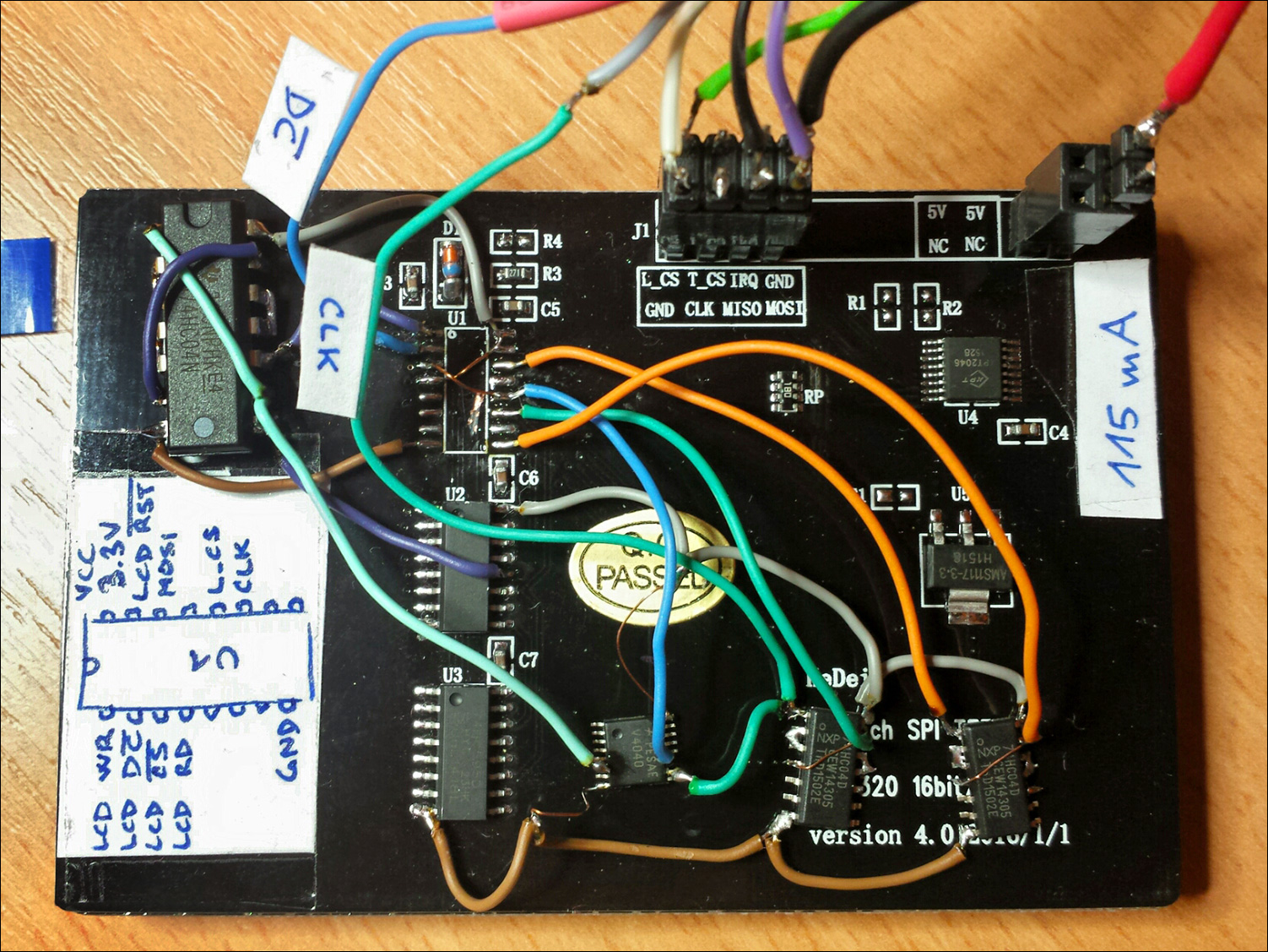
Third prototype hack with fast 74VHC4040 and propagation delay compensation => max 40 MHz CLK!
Use new CLK input, don't connect CLK to original connector.
Limitations:
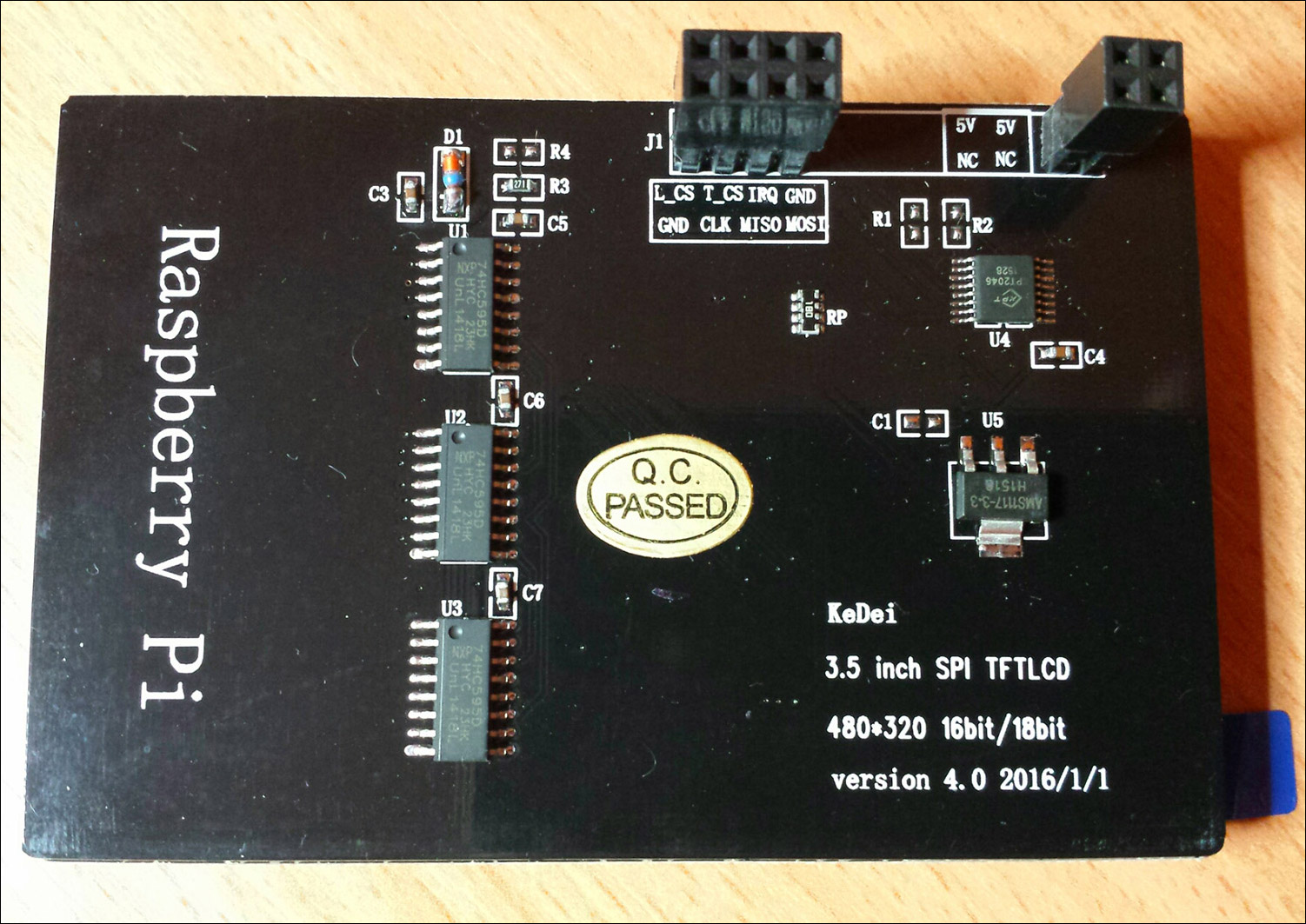
- The KeDei display must be v4.0 (see image in "The hack" section below) - with this version of the module I've done the hack and tested everything. I've tried the same thing with v6.0 - unsuccessfully. The wiring to shift register is different, LCD controller is different. If anyone knows the exact wiring of the control and data signals to shift register for v6.0, please tell me.
- In WLCD driver we're using "only" 65 k colors (R5G6B5) mode, because this gives us speed. A lot of it! Many things can be optimized then and we can use 32-bit copy instructions. Everything is nicely aligned when using R5G6B5 and ESP8266's HSPI
And this could be done as a result, based on this hack. My ESP8266 powered 3.5" 480x320 WiFi LCD (SPI CLK is 40 MHz to LCD module)
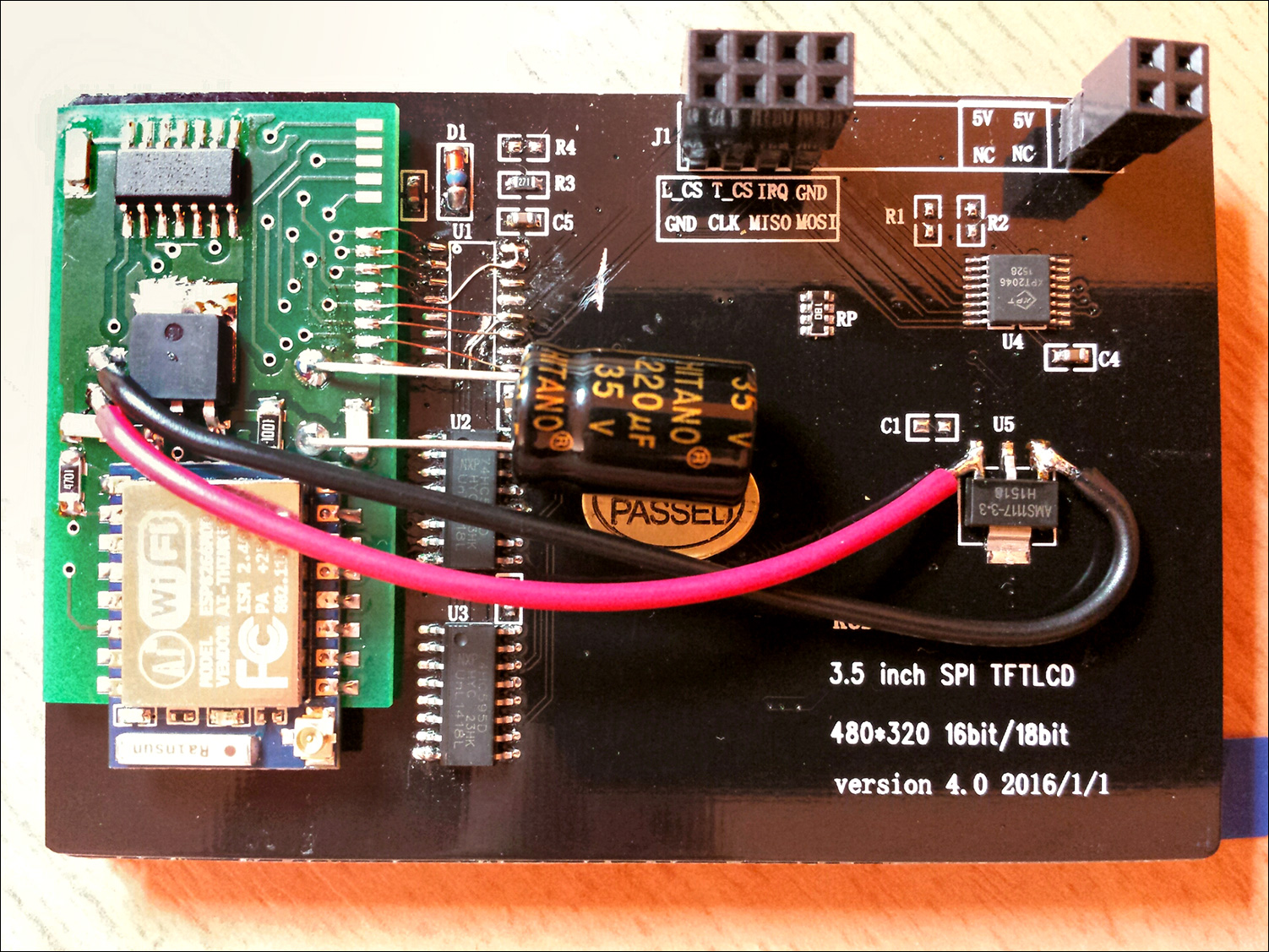
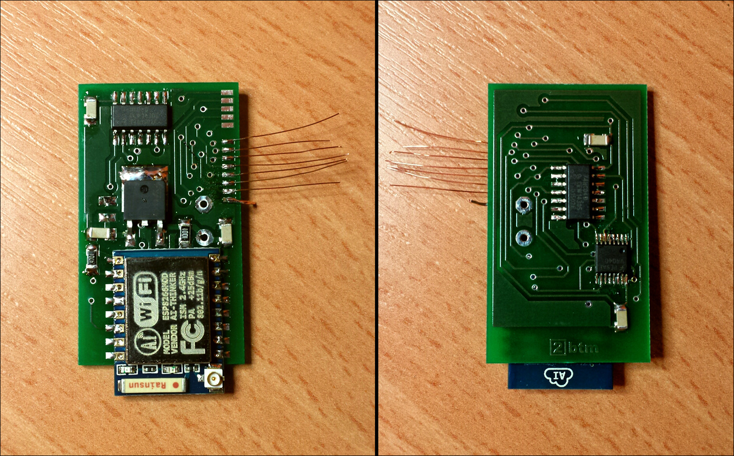 "Serial production" PCB with ESP-07 module connected to hacked KeDei LCD module
##The hack
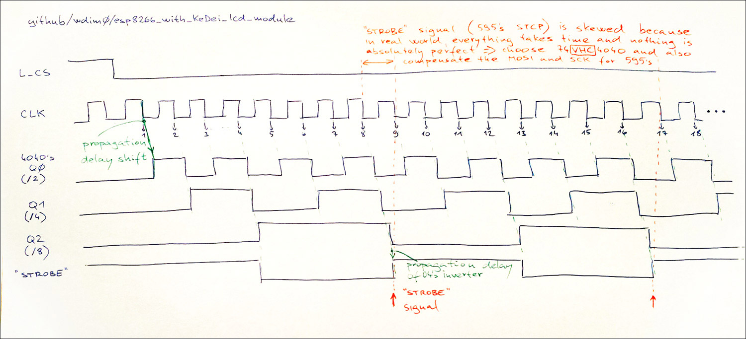
Schema of the hack (not all parts of the display module are drawn (power suppy, touch, connectors, ...). It's not important for the idea of the hack). By the "propagation delay" I mean the delay between the input and output change. For 74HC4040's CP input and Q2 output, it's someting around 40 ns (according to datasheet). For 74VHC4040 it's someting around 10 ns (for VCC = 3.8V, measured).

Timing is becomming important for 74HC... family when speed exceeds tenths of MHz ...
This is an explanation, why we need propagation delay compensation when we want to achieve higher speeds.
Original 3.5" KeDei LCD module
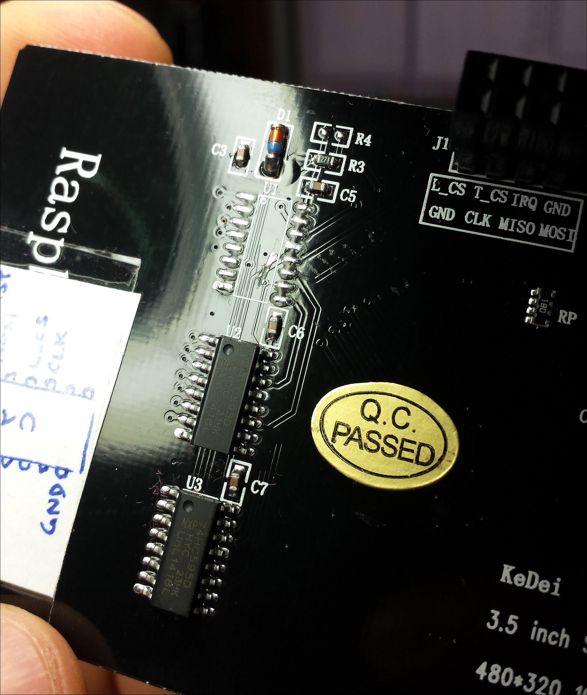
U1 removed (hot air soldering station is your friend). If you want to copy my first/second/third prototype hack, interrupt PCB trace leading L_CS signal from U1 to U2 and U3's STCP input (interrupt between U1 and U2)
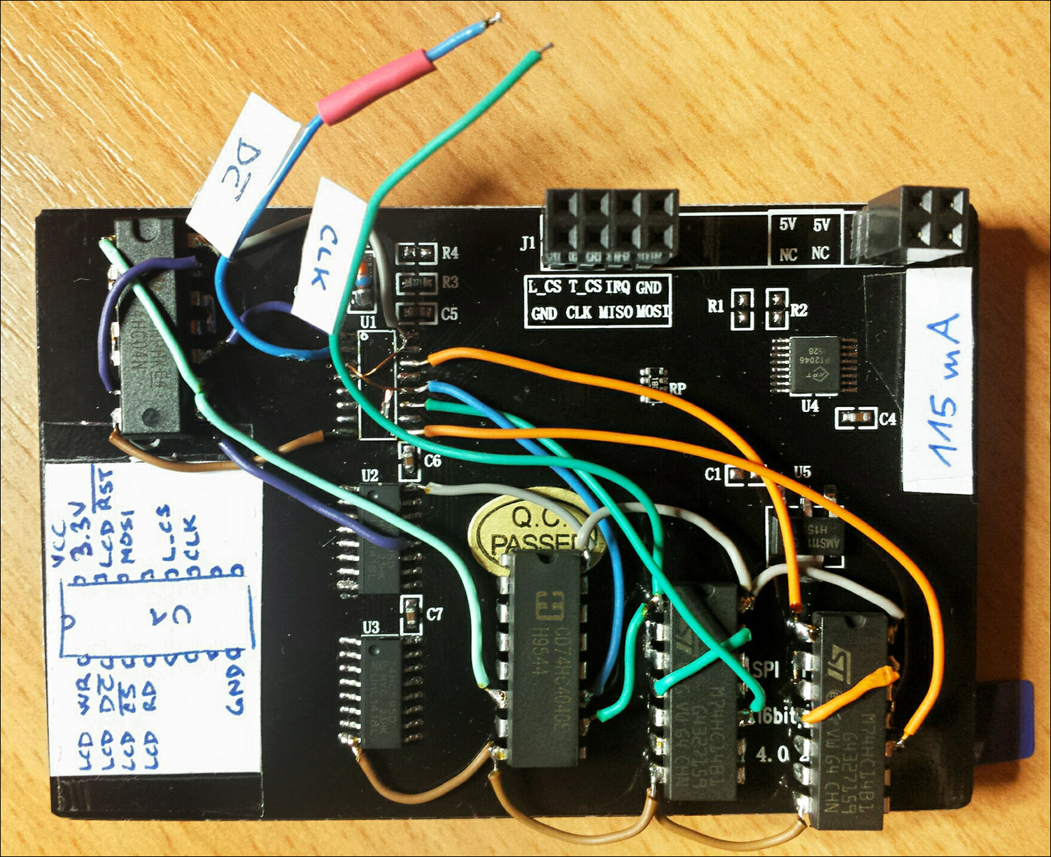
First prototype hack with standard 74HC4040 (and no propagation delay compensation) => max 13.3 MHz CLK

Second prototype hack with standard 74HC4040 and propagation delay compensation => max 20 MHz CLK
Use new CLK input, don't connect CLK to original connector.
13.3 MHz CLK vs 20 MHz CLK comparison using WLCD demo:
1000 lines in 1833 ms vs 1595 ms => +15% faster
1000 images 50x50 in 3345 ms vs 2345 ms => +42% faster
ESP8266 with hacked 3.5" KeDei LCD module (480x320, SPI, 74HC4040 - CLK 20 MHz) - video
Third prototype hack with fast 74VHC4040 and propagation delay compensation => max 40 MHz CLK!
Use new CLK input, don't connect CLK to original connector.

20 MHz CLK vs 40 MHz CLK comparison using WLCD demo:
1000 lines in 1595 ms vs 1291 ms => +19% faster
1000 images 50x50 in 2345 ms vs 1344 ms => +74% faster
ESP8266 with hacked 3.5" KeDei LCD module (480x320, SPI, 74VHC4040 - CLK 40 MHz) - video
This hack would never be possible without great starting point created by saper-2:
https://github.com/saper-2/rpi-spi-lcd35-kedei
https://www.raspberrypi.org/forums/viewtopic.php?f=44&t=124961
Thanks!

