-
Notifications
You must be signed in to change notification settings - Fork 5
Hardware_RFID Reader
example serial communication code on mbed
All tests done with vertical capsule parallel to plane of antenna unless otherwise noted.
- 2.5 cm with 5V usb straight from laptop (capsule vertical parallal to plane of antenna and offset toward top edge)
- 2.5 cm with 5V usb straight from laptop (capsule horizontal into plane of antenna and centered)
- 1.75 cm with 3.3V from arduino
- 1.6 cm with 5V usb to sparkfun rfid board
- 1.0 cm with 5V from arduino
comment on variation of read distance with power supply
sparkfun measurements of read distances
This page describes how to set up an RFID sensor module that reads RFID tags "repeatedly." The original RFID sensor sold by SparkFun can read a tag once when it is in the readable range and again only after it leaves the range and reenters. Using Arduino Leonardo, you can write a program that reads a tag after every user-defined time interval while the tag is within the readable range.
Also, you will integrate the RFID sensor module with the working Electronics Box. (Please refer to the Electronics_box_v3 page for necessary parts and assembly.) The integration process requires two different serial libraries in the Arduino: WebUSB and SoftwareSerial.
RFID Reader ID-20LA (SparkFun, PRT-11828)
RFID Reader Breakout (SparkFun, PRT-13030)
2mm XBee socket (SparkFun, PRT-8272)
USB Type A Male connector + Covers (Conwork, USB-Header-10416)
Wires
(optional)
Female-to-Female Jumper Wires 4-inch & 8-inch (Amazon, Part# B01L5ULRUA)
Male-to-Male Jumper Wires 4-inch (Amazon, Part# B077N6HFCX)
Arduino Leonardo can perform serial communication via its built-in serial ports (digital pin 0 and 1, RX and TX respectively). Hence, if you do not have an additional serial input to the Arduino, you can use the built-in serial ports to talk with the RFID sensor.
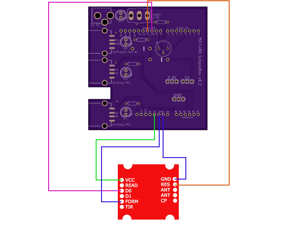
For the sake of integrating the RFID sensor module with the Electronics Box, you need to differentiate between the serial input from your computer/tablet and that from the RFID sensor. The following circuit diagram was designed for this purpose.
RFID CIRCUIT DIAGRAM

D0 of the RFID module sends signals and D1 receives signals. Thus, to read a tag from the sensor, you should connect D0 from the breakout board to one of the digital pins in the Arduino (pin 0 to pin 13).
To read an RFID tag repeatedly, you should connect the RES (Reset) pin from the Breakout board to one of the digital pins of the Arduino board. Essentially, you are resetting the RFID sensor every few seconds or any given time interval.
VCC is the power supply, so it should be connected to 5V of the Arduino.
FORM should be connected to GND to enable the ASCII format output.
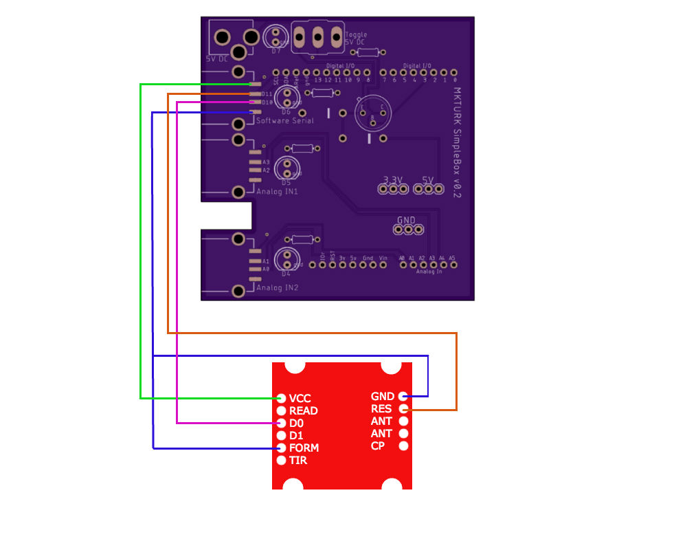
You could use jumper wires to connect the RFID sensor to the Arduino, but you can take advantage of the Software Serial Port on the PCB board. You can find detailed information about the PCB board in Hardware_Electronics Box(v3) page. Pin 10 and 11 are selected deliberately in the above diagram for this reason. You can see that the Software Serial port is connected to power, D10, D11, and GND.
USING SOFTWARE SERIAL PORT

First, solder wires to the appropriate pins of the RFID breakout board. The pins you need to use are VCC, FORM, D0, RES, and GND (RES is not necessary unless you need repeated reading of an RFID tag).
Second, solder the 2mm headers to the RFID breakout board. You could solder the breakout directly to the sensor, but to minimize damage to the sensor itself, you might want to use the sockets.
Third, attach the RFID sensor to the RFID breakout board.

Fourth, solder the other ends of the wires to the appropriate pins of a USB male connector. Both the FORM and GND wires need to be soldered onto the GND pin of the USB connector.
Finally, enclose the USB and wires with a cover to create a stable handle.

First, you need to test if the RFID sensor module works. You need to add the SoftwareSerial library before writing the code and designate the two digital pins as serial communication ports. Upload the sketch below to the Arduino. Make sure you disconnect the RFID sensor from the Arduino during uploading.
#include <SoftwareSerial.h>


SoftwareSerial mySerial(10, 11);
int RFIDResetPin = 11;

char val = 0; // variable to store the data from the serial port

void setup() {
Serial.begin(9600); // connect to the serial port
pinMode(RFIDResetPin, OUTPUT);
digitalWrite(RFIDResetPin, LOW);
digitalWrite(RFIDResetPin, HIGH);
mySerial.begin(9600);
}

void loop () {
// read the serial port
while(mySerial.available() > 0) {
val = mySerial.read();
Serial.write(val);
}
resetReader();
}

void resetReader(){
///////////////////////////////////
//Reset the RFID reader to read again.
///////////////////////////////////
  digitalWrite(RFIDResetPin, LOW);
  digitalWrite(RFIDResetPin, HIGH);
  delay(3000);
}
The code will enable reading of an RFID tag every 3 seconds. You can adjust the time interval for repeated reading by changing delay(3000).
After you successfully upload the sketch, in the Arduino IDE, go to Tools>Serial Monitor. Bring an RFID card/tag near the sensor. You will see 12 ASCII characters in the Serial Monitor window. Keep the tag more than 3 seconds in the range and you will see a 2nd line of the same ID output in the Serial Monitor Window.
Once you confirm that the RFID sensor module works, you can integrate the first code into the working code for the Electronic Box_v3, so that the Arduino can communicate with your tablet and the RFID sensor simultaneously. Now, using the Software Serial port comes in handy because your Arduino needs to differentiate between serial inputs from the tablet and those from the sensor.
Once again, upload the sketch to the Arduino once you disconnect the RFID module. When put in closed loop with the mkturk web app, speeds of 8 Hz (reads every 125ms) are achieved when the tag is in range.
// Arduino code for mkturk:
// Integrated with pump code
// Parses tag from software serial stream to transmit as a word over WebUSB

#include <WebUSB.h>
#include <SoftwareSerial.h>

WebUSB WebUSBSerial(1, "webusb.github.io/arduino/demos");
#define Serial WebUSBSerial

// PUMP
const byte numChars = 32;
char receivedPumpChars[numChars];
boolean newPumpCommand = false;
const int pumpPIN=2;
const int pumpLEDPIN=7;
int pumpdur;

// RFID
const byte numCharsTag = 12;
char receivedRFIDChars[numCharsTag+1]; // variable to store the data from the serial port
boolean newRFIDTag = false;
SoftwareSerial mySerial(10, 11);
int RFIDResetPin = 11;

char startMarker = '{';
char endMarker = '}';

void setup() {
  pinMode(pumpPIN, OUTPUT);
  pinMode(pumpLEDPIN, OUTPUT);
  while (!Serial) {
    ;
  }
  Serial.begin(9600);
  Serial.println("<Arduino is ready> Sketch begins \r\n>");
  Serial.flush();

  pinMode(RFIDResetPin, OUTPUT);
  digitalWrite(RFIDResetPin, LOW);
  digitalWrite(RFIDResetPin, HIGH);
  mySerial.begin(9600);
}

void loop() {
  // receive pump || rfid data
  recvWithStartEndMarkers();
  readRFIDTag();

  // act on pump || rfid
  turnOnPump();
  transmitTag();
  resetReader();
}

// PUMP
void recvWithStartEndMarkers() {
    static boolean recvInProgress = false;
    static byte ndx = 0;
    char rc;

    while (Serial && Serial.available() > 0 && newPumpCommand == false) {
        rc = Serial.read();

        if (recvInProgress == true) {
            if (rc != endMarker) {
                receivedPumpChars[ndx] = rc;
                ndx++;
                if (ndx >= numChars) {
                    ndx = numChars - 1;
                }
            }
            else {
                receivedPumpChars[ndx] = '\0'; // terminate the string
                recvInProgress = false;
                ndx = 0;
                newPumpCommand = true;
            }
        }

        else if (rc == startMarker) {
            recvInProgress = true;
        }
    }
}

void turnOnPump() {
  if (newPumpCommand == true) {
    Serial.print("Received from WebUSB ... ");
    Serial.println(receivedPumpChars);
    Serial.flush();

    pumpdur = atoi(receivedPumpChars);
    digitalWrite(pumpPIN,HIGH);
    digitalWrite(pumpLEDPIN,HIGH);
    delay(pumpdur);
    digitalWrite(pumpPIN,LOW);
    digitalWrite(pumpLEDPIN,LOW);
    newPumpCommand = false;

    Serial.print("Pump triggered, dur=");
    Serial.print(pumpdur);
    Serial.flush();
  }
}

// RFID
void readRFIDTag() {
  static boolean recvInProgress = false;
  static byte ndx = 0;
  char startMarker = '0';
  char rc;

  while(mySerial.available()>0 && newRFIDTag == false) {
    rc = mySerial.read();

    if (recvInProgress == true){
      if (ndx < numCharsTag){
        receivedRFIDChars[ndx] = rc;
        ndx++;
      }
      else {
        receivedRFIDChars[ndx] = '\0'; // terminate the string
        ndx = 0;
        recvInProgress = false;
        newRFIDTag = true;
      }
    }

    else if (rc == startMarker){
      recvInProgress = true;
      ndx=0;
      receivedRFIDChars[ndx] = rc;
      ndx++;
    }
  }
}

void transmitTag(){
  if (newRFIDTag == true){
    Serial.print("Received RFID Tag on SoftwareSerial ... ");
    Serial.print(startMarker);
    Serial.print("tag");
    Serial.print(receivedRFIDChars);
    Serial.println(endMarker);
    Serial.flush();
  }
}

//Reset the RFID reader to read again.
void resetReader(){
  if (newRFIDTag == true){
    digitalWrite(RFIDResetPin, LOW);
    digitalWrite(RFIDResetPin, HIGH);
    newRFIDTag = false;
  }
}Although you can use the off-the-shelf SparkFun Breakout board like above, we decided to manufacture our own Breakout board for the sake of a modular design.
EAGLE BOARD
OSHPARK TOP
The board includes a surface-mounted microUSB connector which effectively replaces soldering of wires, and an LED that lights up whenever a tag is read.
COMPLETE ASSEMBLY