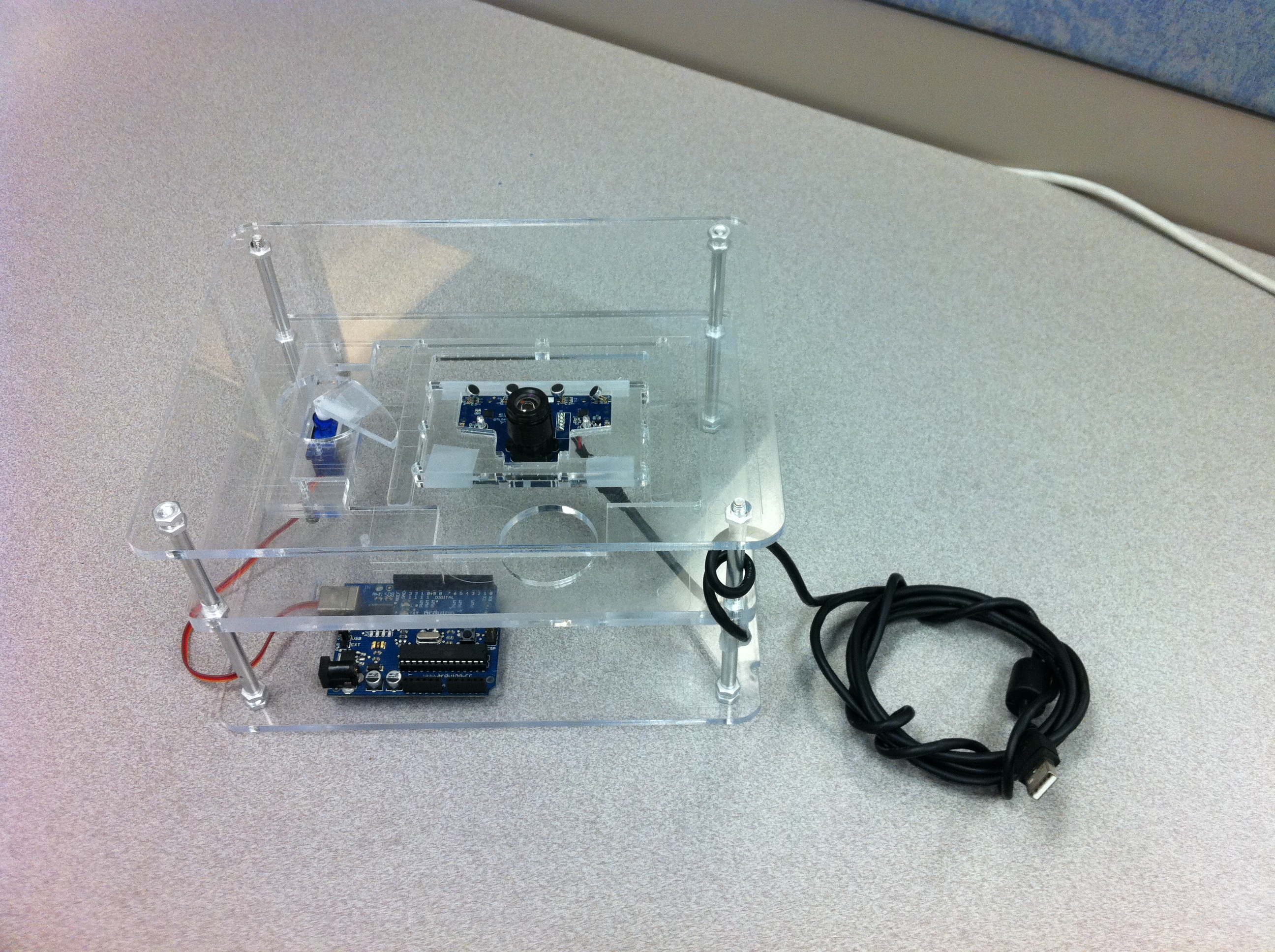
A low-cost 2-axis motion stage designed to be entirely laser-cuttable (just add servos) & a processing sketch for controlling servos.
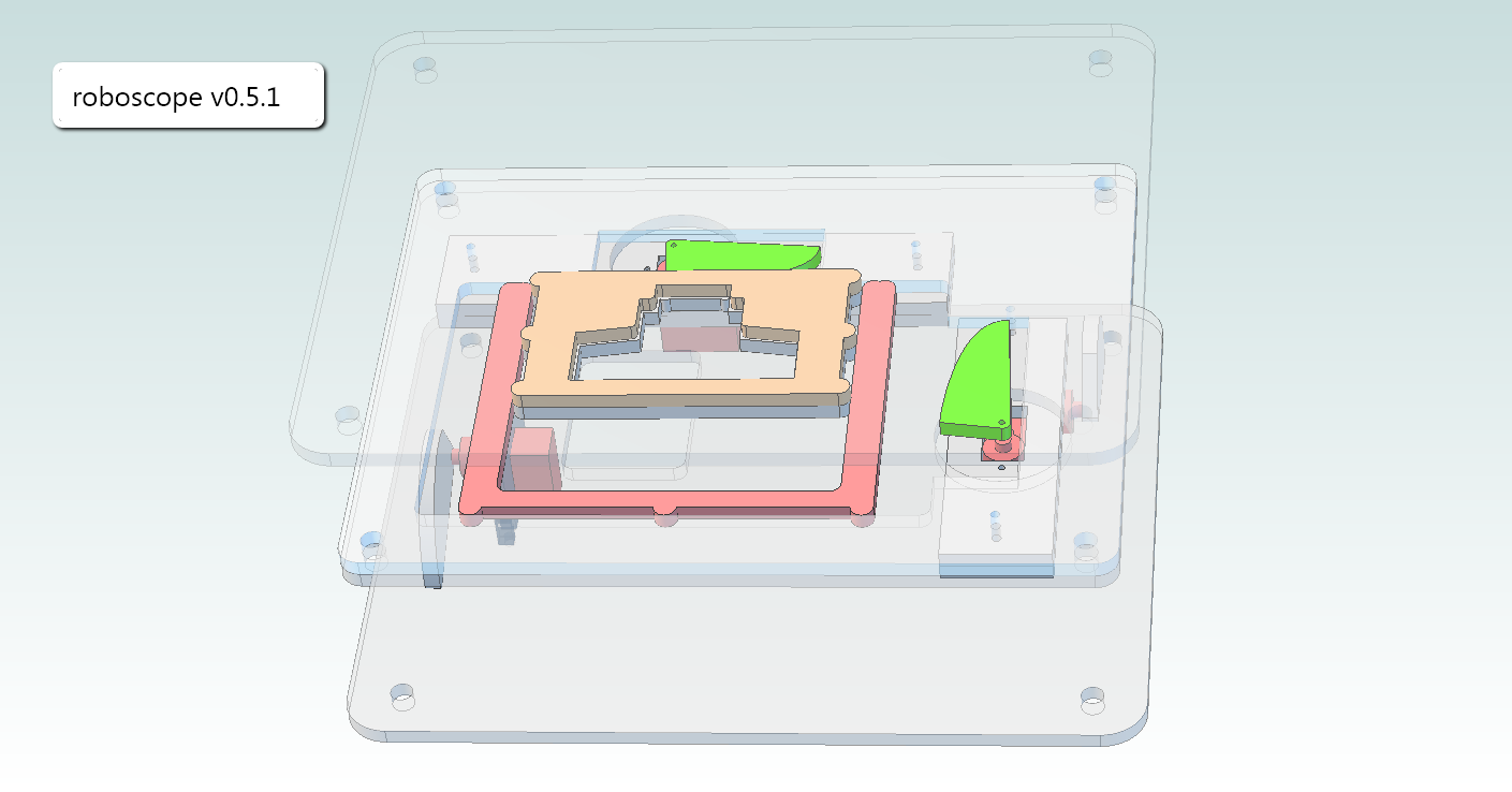
Key distinctions with this design are that both the x- and the y-stage are in the same plane, i.e. they are not stacked on one another. Cams cut with an Archimede's spiral linearly translate rotational motion from stepper motors into linear displacement.
(The design pictured below also depicts a z-axis - which turned out to be overconstrained as designed - and this repo only includes vector files for a 2-axis stage).
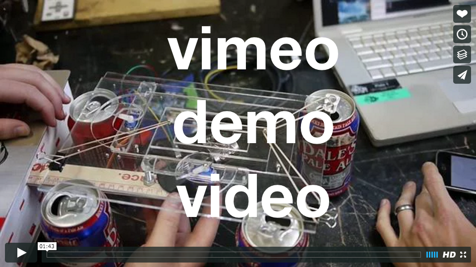
 **[demo video](https://vimeo.com/11139943)**ucam_ps3.pde displays the videostream from a modded ps3eye microscope via USB, accepts mouse clicks and drags as user input, and controls a 2-axis servo-powered microscope slide stage via an arduino w/ firmata firmware
Note: The assembly pictured above was originally modeled in Alibre back in 2010. I hope to convert these to a more usable format (shouldn't be too hard to reconstruct using the design files in this repo). The original alibre AD_PRT and AD_ASM files are available in a separate repo: 100ideas/ucam-alibre-cad.
-
processing ide: http://processing.org/download/
-
video, serial, and arduino libraries for processing (included by default): http://processing.org/reference/libraries/.
-
arduino ide: http://arduino.cc/en/Main/Software
-
ucam hardware platform: http://diybio.org/ucam
-
modded ps3eye: http://www.dusseiller.ch/labs/?p=912 (I used a small spot of superglue to lightly secure the inverted lens to the lens mount).
-
get acrylic, nuts & bolts, rubber band, webcam, servos, arduino.
-
cut stage from acrylic sheet using design files.
-
assemble. optionally glue cams to servo horns. attach rubber bands to provide tension (see video).
-
upload ServoFirmata_9_11.pde to your arduino and connect the servo control wires to the +5v, ground, and digital pins 9 and 11. You will want a breadboard to breakout the power bus to the servos.
On TPro SG90 or HTX900 microservos, the wiring colors correspond to:
- yellow: control
- red: 5 volts
- brown: ground
- run ucam_ps3.pde in processing and click around.

